
The reflection coefficient value is specifically essential when working with RF frequencies. In cases where the impedance cannot be considered directly, the reflection coefficient (symbolized by Γ L) of parameters like admittance, gain, as well as trans-conductance can be used to characterize the load. Here, Z 0 is the value for the impedance of the transmitter, and Z L represents the impedance of the load. The reflection coefficient value can be generated from the equation as below On a more technical perspective, a smith chart incorporates a polar plot of complex reflection coefficient (symbolized by Γ) and is implemented by inspecting the load whose impedance must be matched.

Additionally, parameters like admittance, scattering values, analysis of mechanical vibrations, noise figure circles, and reflection coefficients can be simultaneously exhibited with the help of the charts.

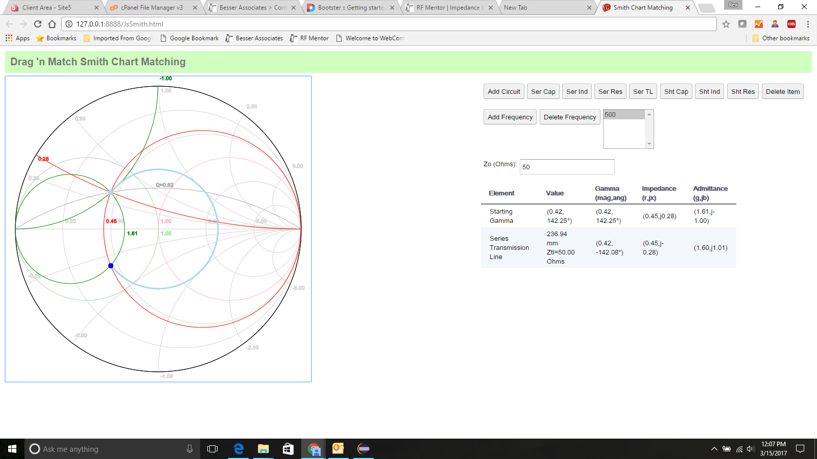
Impedance matching is the chief and consistently used offering from Smith charts along with designing, tuning and validation of similar networks. Example: Impedance Smith Chart (Image Source: ) Each of the circular structure either denotes the constant resistance or constant reactance. In simple terms, the graph can be considered a collection of circles, where each of the circle is placed at different locations in the plot area. The chart is a basically circular structure constituting of two major circles or arcs, namely the Constant R Circles and the Constant X Circles that help to visually define the shape and the data values incorporated in the chart.

The chart was acknowledged as a transmission line calculator owing to its prime purpose of use. It can be most importantly touted as a graphical tool or calculator that assists in displaying and understanding the impedance and frequency values associated with transmission lines with the help of equations. The charts were brought to limelight in the wake of World War II to evaluate the problems associated with the transmission of radio waves.Ī Smith chart can largely be identified as a diagrammatic illustration revolving around the behavior of transmission lines. Coined and developed by Paul Smith, smith charts were essentially deployed to provide electrical, microwave and electronic engineering solutions much before the advent of digital computers.


 0 kommentar(er)
